 Aerated Concrete Block Industry
 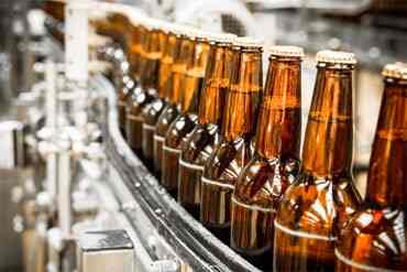 Brewery Industry
  Captive Cogen Industry
 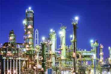 Chemical Industry
  Dairy Industry
 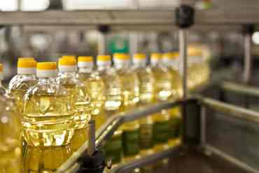 Edible Oil Industry
 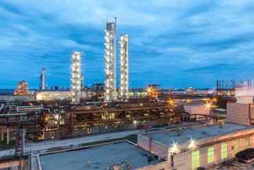 Fertilizer Industry
  Hotel Industry
  Pharma Industry
 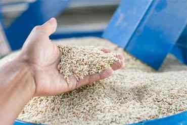 Rice Industry
  Rubber Industry
  Soap Industry
 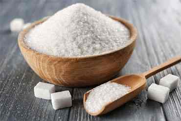 Sugar Industry
  Textile Industry
  Tyre Industry
 SMU-7000 Safety Relief Valve
- Home
- Products
- Safety Valve & Control Valve Division
- UKL-AST Safety Relief Valve
- SMU-7000 Safety Relief Valve
- The Model SMU 7000 is approved by Indian Boiler Regulation 1950.
- Full Nozzle & Full Lift Design.
Safety and Pressure -relief valves should be installed vertically with the drain holes open or piped to a convenient location. All piping must be fully supported.
Maintenance should be performed on a regular basis. An initial inspection interval of no longer than 12 months is recommended. The user must establish an appropriate inspection interval depending on the service conditions, the condition of the valve and the level of performance desired.The ASME Boiler and Pressure Vessel Code does not require nor address testing installed valves. The only thing the code states are design and installation requirements, such as some valves must have a lifting lever. For instance for Section VIII:“Each pressure relief valve on air, water over 140° F, or steam service shall have a substantial lifting device which when activated will release the seating force on the disk when the pressure relief valve is subjected to a pressure of at least 75% of the set pressure of the valve.”
Installing a safety valve in any position other than with the spindle vertical and upright may adversely affect performance and lifetime.
This drain hole is required on some models by the ASME Boiler and Pressure Vessel Code. It is intended to prevent any condensate from accumulating in the body that may freeze or corrode internal valve parts and prevent the valve from opening. The drain hole should be piped away to safely dispose of any discharge or condensate.
Typically, the valve should be nameplate set to open at the MAWP (Maximum Allowable Working Pressure) of the vessel the valve is intended to protect. There is a tolerance to actual set pressure.
Maintain a minimum operating gap of 10% between the system operating pressure and the safety valve’s nameplate set pressure. Since direct spring-operated safety valves may “simmer” or “warn” at 90% of the nameplate set pressure, and since the factory standard leak test is performed at 90% of nameplate set pressure, better seat tightness performance can be expected with an operating gap of 10%.
It may not be. Warn/simmer or seat leakage is sometimes mistaken for set pressure. Visible or audible leakage or system pressure drop is not set pressure. The correct definition of set pressure is:
· For steam or most valves in air/gas service, “pop” (an audible loud pop) – SMS 7100
· For liquid service, first vertical steady stream
· For some valves in air/gas service (SMU -7000 ), first audible
Rapid increases in system pressure (more than 2 psig/second, water hammer, reciprocating pumps) can make the valve appear to be opening early because the gage cannot accurately report the pressure to which the valve is exposed.
Yes. Section I valves have more stringent setting blowdown requirements and may be used in Section VIII steam applications since they meet all the requirements as specified in Section VIII UG-125(a) “Pressure Relief Devices,” which states pressure relief devices must be “in accordance with the requirements of UG-125 through UG-137.” In addition, UG-125(b) actually specifies that even unfired steam boilers MUST use a Section I pressure relief device.
Section VIII UG-136(a)(3) states, “Each pressure relief valve on air, water over 140° F (60° C), or steam service shall have a substantial lifting device which when activated will release the seating force on the disk when the pressure relief valve is subjected to a pressure of at least 75% of the set pressure of the valve.”
· The user has a documented procedure and an associated implementation program for the periodic removal of the pressure relief valves for inspection and testing, and repair as necessary.
· The omission is specified by the user.
· The user shall obtain permission to omit the lifting device from the authority having jurisdiction over the installation of pressure vessels.
Back pressure reduces set pressure on a one-to-one basis, i.e., a valve set at 100 psig subjected to a backpressure at the outlet of 10 psig will not actuate until system pressure reaches 110 psig. Back pressure drastically reduces capacity; typically backpressure of 10% of set pressure will decrease capacity by 50%. Specific capacity reduction should be determined by the user on a case-by-case basis by flow testing. Back pressure in excess of 10% of set pressure is not recommended.
Additional Information
- The Model SMU 7000 is approved by Indian Boiler Regulation 1950.
- Full Nozzle & Full Lift Design.
Downloads
FAQ
Safety and Pressure -relief valves should be installed vertically with the drain holes open or piped to a convenient location. All piping must be fully supported.
Maintenance should be performed on a regular basis. An initial inspection interval of no longer than 12 months is recommended. The user must establish an appropriate inspection interval depending on the service conditions, the condition of the valve and the level of performance desired.The ASME Boiler and Pressure Vessel Code does not require nor address testing installed valves. The only thing the code states are design and installation requirements, such as some valves must have a lifting lever. For instance for Section VIII:“Each pressure relief valve on air, water over 140° F, or steam service shall have a substantial lifting device which when activated will release the seating force on the disk when the pressure relief valve is subjected to a pressure of at least 75% of the set pressure of the valve.”
Installing a safety valve in any position other than with the spindle vertical and upright may adversely affect performance and lifetime.
This drain hole is required on some models by the ASME Boiler and Pressure Vessel Code. It is intended to prevent any condensate from accumulating in the body that may freeze or corrode internal valve parts and prevent the valve from opening. The drain hole should be piped away to safely dispose of any discharge or condensate.
Typically, the valve should be nameplate set to open at the MAWP (Maximum Allowable Working Pressure) of the vessel the valve is intended to protect. There is a tolerance to actual set pressure.
Maintain a minimum operating gap of 10% between the system operating pressure and the safety valve’s nameplate set pressure. Since direct spring-operated safety valves may “simmer” or “warn” at 90% of the nameplate set pressure, and since the factory standard leak test is performed at 90% of nameplate set pressure, better seat tightness performance can be expected with an operating gap of 10%.
It may not be. Warn/simmer or seat leakage is sometimes mistaken for set pressure. Visible or audible leakage or system pressure drop is not set pressure. The correct definition of set pressure is:
· For steam or most valves in air/gas service, “pop” (an audible loud pop) – SMS 7100
· For liquid service, first vertical steady stream
· For some valves in air/gas service (SMU -7000 ), first audible
Rapid increases in system pressure (more than 2 psig/second, water hammer, reciprocating pumps) can make the valve appear to be opening early because the gage cannot accurately report the pressure to which the valve is exposed.
· For steam or most valves in air/gas service, “pop” (an audible loud pop) – SMS 7100
· For liquid service, first vertical steady stream
· For some valves in air/gas service (SMU -7000 ), first audible
Rapid increases in system pressure (more than 2 psig/second, water hammer, reciprocating pumps) can make the valve appear to be opening early because the gage cannot accurately report the pressure to which the valve is exposed.
Yes. Section I valves have more stringent setting blowdown requirements and may be used in Section VIII steam applications since they meet all the requirements as specified in Section VIII UG-125(a) “Pressure Relief Devices,” which states pressure relief devices must be “in accordance with the requirements of UG-125 through UG-137.” In addition, UG-125(b) actually specifies that even unfired steam boilers MUST use a Section I pressure relief device.
Section VIII UG-136(a)(3) states, “Each pressure relief valve on air, water over 140° F (60° C), or steam service shall have a substantial lifting device which when activated will release the seating force on the disk when the pressure relief valve is subjected to a pressure of at least 75% of the set pressure of the valve.”
· The user has a documented procedure and an associated implementation program for the periodic removal of the pressure relief valves for inspection and testing, and repair as necessary.
· The omission is specified by the user.
· The user shall obtain permission to omit the lifting device from the authority having jurisdiction over the installation of pressure vessels.
· The user has a documented procedure and an associated implementation program for the periodic removal of the pressure relief valves for inspection and testing, and repair as necessary.
· The omission is specified by the user.
· The user shall obtain permission to omit the lifting device from the authority having jurisdiction over the installation of pressure vessels.
Back pressure reduces set pressure on a one-to-one basis, i.e., a valve set at 100 psig subjected to a backpressure at the outlet of 10 psig will not actuate until system pressure reaches 110 psig. Back pressure drastically reduces capacity; typically backpressure of 10% of set pressure will decrease capacity by 50%. Specific capacity reduction should be determined by the user on a case-by-case basis by flow testing. Back pressure in excess of 10% of set pressure is not recommended.


SMU-7000
Installation for SECTION VIII requirement for Unfired vessels , applicable for Gas , Liquid , Steam & biphase
Catalog